- On Windows:
- Download and install Eclipse IDE for C/C++ Developers (today, the latest is Mars 2)
- Download and install WinAVR (today, the latest is 20100110)
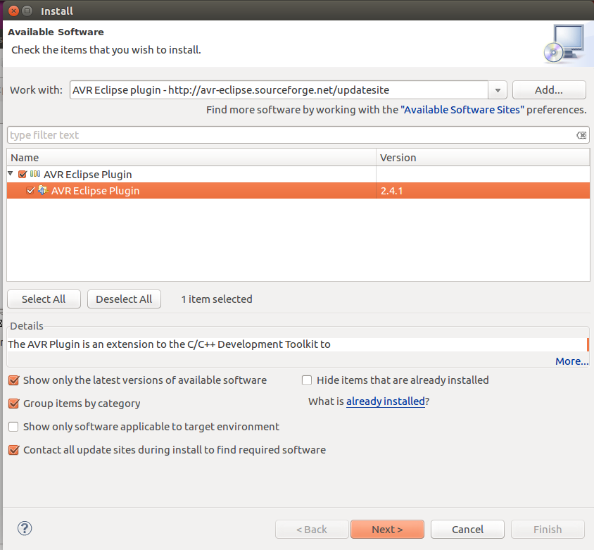
- Open Eclipse, go to Help > Install New Software.... Add the following to the "Work with" section: http://avr-eclipse.sourceforge.net/updatesite and install the plugin.
- Done!
- On Linux (Ubuntu in my case):
- Install Eclipse
- sudo apt-get install eclipse
- Install AVR compiler
- sudo apt-get install avrdude binutils-avr gcc-avr avr-libc gdb-avr
- Open Eclipse, go to Help > Install New Software.... Add the following to the "Work with" section: http://avr-eclipse.sourceforge.net/updatesite and install the plugin.
- Add your user to the dialout group, then logout and login again (this is in order to your user have permission to access the serial port).
- sudo usermod -a -G dialout <username>
- Done!
Wait, what? This is it? Yep! Unless you didn't install WinAVR on its default location (C:/WinAVR-20100110). In that case, you'll need to adjust the paths in the AVR Eclipse plugin (on Eclipse, go to Window > Preference > AVR > Paths):
- AVR-GCC: <WinAVR path>\bin
- GNU make: <WinAVR path>\utils\bin
- AVR Header Files: <WinAVR path>\avr\include
- AVRDude: <WinAVR path>\bin

Yes, this screen is from Ubuntu.
Now let's create a first project just to check whether it works. Can you guess? A Blink project! This time, we won't use any of the easy Arduino stuff. Instead, let's open the microcontroller datasheet and start configuring the registers. In Eclipse, go to File > New > C++ Project (in Linux, you'll go to File > New > Project and choose C++ Project under C/C++ Folder).
- Choose the Empty Project under the folder "AVR Cross Target Application"
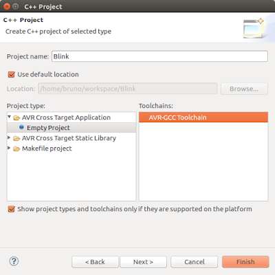
- Pick a name (Blink) and a location
- Click Next
- Click Next again
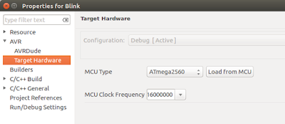
- Choose the MCU (ATmega2560) and Frequency (16000000 - that's 16 followed by 6 zeroes, 16MHz)
- Click Finish
- Go to the project properties (click with the left button on the project and go to Properties)
- Under AVR > Target Hardware you can check if the MCU and frequency were correctly chosen
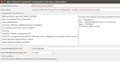
- Under AVR > AVRDude, in the box Programmer Configuration, click New....
- Choose the bootloader version (Atmel STK500 Version 2.x firmware), choose a name for the configuration, choose the correct COM port in "Override default port" (use the Device Manager in Windows -i.e. COM18 -, or, in Linux, the command line "dmesg | grep tty" and remember to put "/dev/" before the port name - i.e. /dev/ttyUSB0), and override default baudrate with 115200 and click OK.
- Still on the Project Properties, go to C/C++ Build > Settings. On the tab Tool Settings:
- Additional Tools in Toolchain, check "Generate HEX file for Flash memory"
- AVR Compiler > Optimization, Optimization Levels: Size Optimization (-Os), uncheck Pack Structs and Short Enums
- AVR Compiler > Language Standard, uncheck "char is unsigned" and "bitfields are unsigned"
- Do the same to AVR C++ Compiler
- Now for the source code files, click with the left button on the project folder (in Project Explorer) and go to New > Folder, choose the project and the name ("src") and click Finish. Again in the Project Explorer, left click on new folder and New > Source File, choose the name ("blink.cpp") and Finish.
- Copy the following source code to your file.
#include <avr/io.h> #include <avr/interrupt.h> int main(void) { //Setup the clock (timer 1, 62.5kHz (16MHz / 256 = 62.5kHz), CTC mode, interrupt on) cli(); //Disable global interrupts TCCR1A = 0b00000000; //no physical outputs (COM1Ax, COM1Bx and COM1Cx == 0b00), WGM10 and WGM11 = 0. TCCR1B = 0b00001000; //input capture off, WGM13 = 0, WGM12 = 1, prescaler 1/256 (CS1x = 0b100 - off by now, thus 0b000) TCCR1C = 0b00000000; //writing a 1 to any of the 3 most significative bits forces a compare match TCNT1 = 0x0000; //resets the timer counter OCR1A = 62499; //Count 62500 cycles for 1 second interrupt OCR1B = 0x0000; //output compare register B is not used OCR1C = 0x0000; //output compare register C is not used ICR1 = 0x0000; //input capture not used TIMSK1 = 0b00000010; //input capture interrupt off, output compare B and C interrupts off, output compare A interrupt on, overflow interrupt off TIFR1 = 0x00; //resets the interrupt flags TCCR1B |= 0b00000100; //turn on the timer (CS1x = 0b100) sei(); //Enable global interrupts //Setup the I/O for the LED (digital pin 13, or PB7, according to the Arduino pin mapping) DDRB = 0b10000000; //PB7 is digital pin 13 (LED), configured as an output PORTB |= 0b10000000; //Set PB7 high to turn on LED while(1) { } //Loop forever, interrupts do the rest } ISR(TIMER1_COMPA_vect) //Interrupt Service Routine - flag is cleared automatically { PORTB ^= (1<<PB7); //Use xor to toggle the LED } - Build it (Ctrl+B)
- Edit: If you're using Windows 10 (or other versions) and encountered this error: make: *** [src/blink.o] Error -1073741502, follow the steps on this post.
- To transfer to the board, there's a little catch (in Windows): seems like Arduino IDE uses a modified version of AVRDude that resets the board before attempting to upload the HEX file (this is needed in order to the Arduino enter the bootloader). So, if you get this timeout message, just hold the reset button on your board and release when you click the Upload button (that's the AVR button with an arrow pointing downwards, or CTRL+ALT+U).
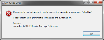
avrdude: stk500_2_Receive_Message(): timeout - Now modify the OCR1A to 6249, compile and upload again: The timer will run 10 times faster, thus the LED must blink faster, if it doesn't, well...find out what's wrong and tell me in the comments box :)


Right now you should have a working hardware, with a working IDE and burner (close enough).
The project is available on GitHub.
On the next post, let's talk business and start porting the FreeRTOS.
The project is available on GitHub.
On the next post, let's talk business and start porting the FreeRTOS.
No comments:
Post a Comment